
Product family
EMI Shielding Covers
Shielding cans, covers and frames in nickel silver, copper alloy and plated steel, with the seam and contact edge controlled.
Direct answer: we make EMI shielding covers, cans and frames from 0.2 to 1.5 mm nickel silver, copper alloy, brass and tin-plated steel, formed to ±0.05 mm and supplied with or without solderable or conductive coating. Frames, lids and multi-cavity shields are produced by stamping for volume or laser cutting and forming for prototypes.
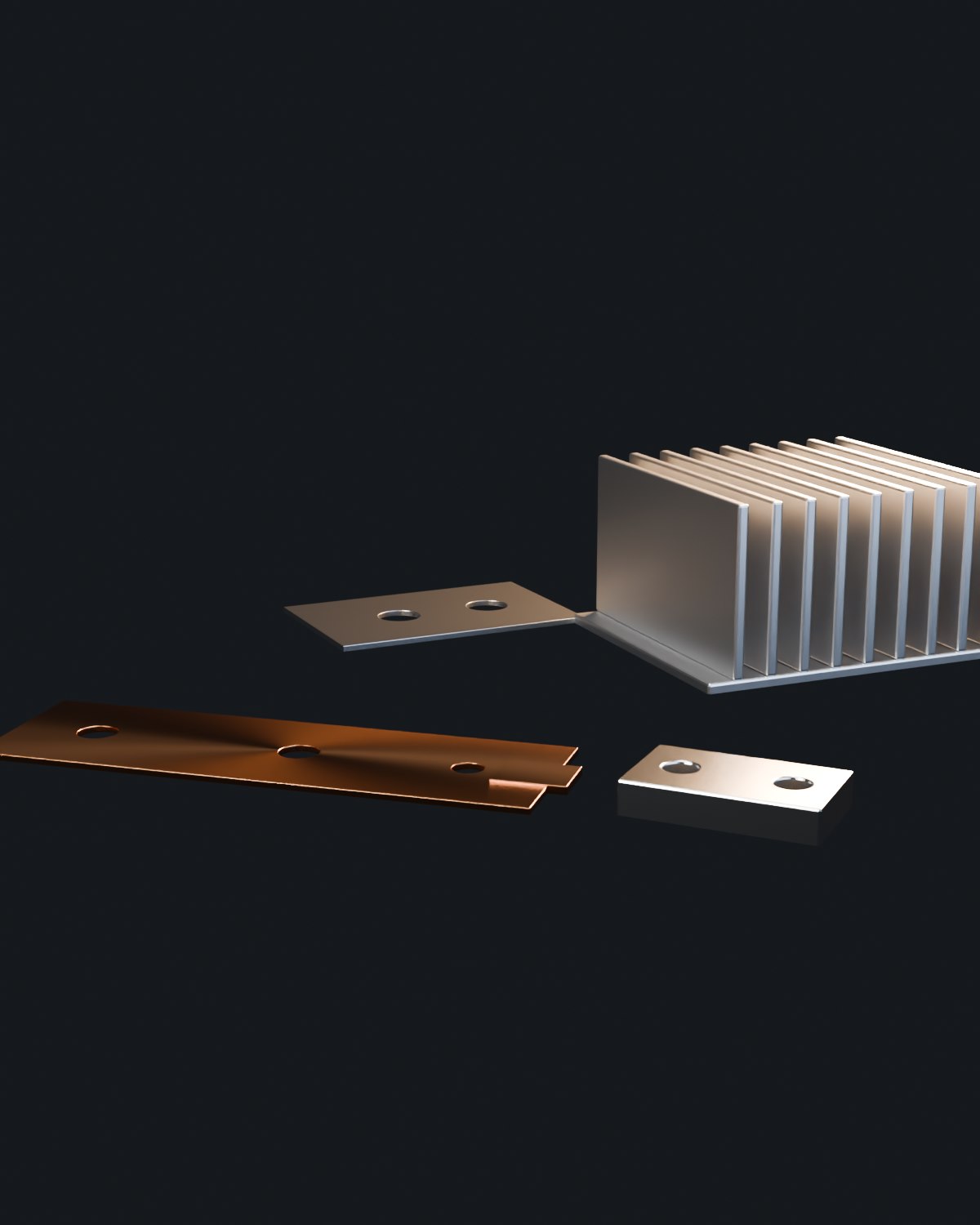
What we make
- Multi-cavity shielding cans and fences
- Removable lids and snap-on covers
- Single-piece drawn shields for small modules
- Shielding frames that are soldered to the PCB
- Contact fingers and grounding clips
- Shielding covers combined with a heat spreader
Specification range
| Parameter | Range / value | Note |
|---|---|---|
| Material | Nickel silver, C2680 brass, C11000 copper, tin-plated steel | Nickel silver for solderability and shielding |
| Thickness | 0.2 – 1.5 mm | Thinner than 0.2 mm quoted as special |
| Profile tolerance | ±0.05 mm | Height of the wall ±0.05 mm |
| Coating | Tin plating 1 – 10 µm, nickel 3 – 10 µm, bare | Coating on the contact edge affects grounding |
| Volume | Prototype to millions per year | Stamped for volume, formed sheet for prototypes |
| Packing | Tray or tape on reel | Nesting agreed to protect the walls |
What decides whether a shield works
Shielding effectiveness depends on the seam and the grounding path more than on the material thickness. A wall with a gap, a bent contact edge or a coating that insulates the contact point will leak regardless of the alloy. We control wall height, edge straightness and coating thickness on the contact edge for that reason.
Design rules
- Give the seam design and the grounding method – solder, conductive gasket or spring fingers.
- Keep the contact edge free of thick coating, or specify masking; plating thickness closes the gap.
- Allow a draft or relief at the corner radius; a sharp inside corner cracks during forming.
- State the lid retention method and the number of openings expected, so the finger geometry is designed for it.
- For multi-cavity shields, give the wall thickness between cavities – it sets the minimum material thickness.
Frequently asked questions
Which material is best for a shielding can?
Nickel silver and brass are the usual choices for shielding cans because they form well, solder easily and conduct; tin-plated steel is cheaper for larger covers where solderability is less critical. The choice is stated in the quotation with the shielding and solderability reasons.
Can you supply the shield with a conductive coating?
Yes – tin, nickel or a conductive finish is applied, and the contact edge can be masked if the coating would insulate the grounding point. The requirement is defined on the drawing.
What is the usual volume range for a stamped shield?
Stamped shields make sense from roughly 10,000 pieces a year, where the die cost is recovered. Below that, laser cutting and forming is quoted, which avoids tooling but has a higher unit price.
Send the shield drawing and the grounding method
Seam design, contact edge and coating decide whether the shield works. Include them with the drawing.