Product family
Battery Cell Connectors
Cell connectors, module links and busbar assemblies for battery packs, where the weld pad and the contact face decide the joint quality.
Direct answer: we make battery cell connectors and module links in copper, nickel-plated copper and aluminium, from 0.3 to 3 mm, with the weld pad and contact face kept flat and burr-free. Tolerance is ±0.05 mm on the contact and weld areas, plating is nickel or silver from 1 to 5 µm, and parts are supplied loose or on tape for automated lines.
What we make
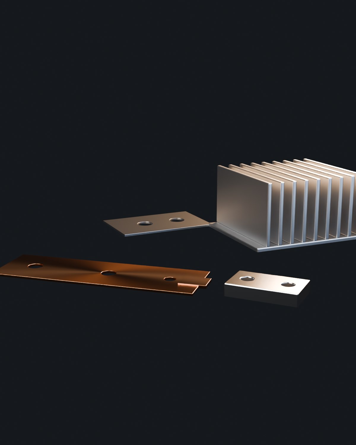
- Cell-to-cell connectors for cylindrical and prismatic cells
- Module links and inter-module busbars
- Nickel-plated copper connectors for laser or ultrasonic welding
- Aluminium connectors for cell tabs where weight matters
- Connector assemblies with insulation film or heat shrink
- Fuse-integrated and sense-wire connectors on request
Specification range
| Parameter | Range / value | Note |
|---|---|---|
| Material | C11000 copper, nickel-plated copper, 1060 aluminium | Nickel plating 1 – 5 µm on copper weld pads |
| Thickness | 0.3 – 3 mm | Thinner parts quoted as stamped |
| Contact and weld face | Flatness 0.05 mm, burr 0.05 mm max | Both controlled on the drawing |
| Profile tolerance | ±0.05 mm | Hole position ±0.05 mm |
| Volume | Prototype to millions per year | Stamped for volume, laser cut for prototypes |
| Packing | Loose, tray or tape on reel | Tape pitch agreed for automated assembly |
Why the weld pad matters more than the outline
A connector that is 0.3 mm out of position can still weld, but a weld pad with a burr or a raised edge produces a weak joint that fails in the field. That is why we control flatness, burr height and cleanliness on the pad, and inspect them per batch rather than relying on the general tolerance.
Process route
1. Stamping or laser cutting
Stamped for volume with the die designed around the pad and hole pattern; laser cut for prototypes.
2. Deburring
Tumble or brush deburr, with the pad surface protected so it stays flat.
3. Plating
Nickel or silver on the pad, masked elsewhere if the drawing requires.
4. Forming
Bends formed after plating where the bend area must stay unplated, or before plating where coverage is needed.
5. Inspection
Pad flatness, burr height, hole position and plating thickness on a sample per batch.
Design rules
- Give the pad geometry and the welding process – laser, ultrasonic and resistance welding need different surface conditions.
- State burr direction and limit on the pad face; a burr on the weld side is worse than on the outside.
- Define the bend radius relative to material temper; hard copper cracks at tight radii.
- Allow for plating thickness if the connector locates in a fixture or a cell holder.
- Specify the packing method if the parts go into an automated line – tape pitch, orientation and reel size.
Frequently asked questions
Which welding process do your connectors suit?
The surface condition is specified to the welding process you use – laser welding needs a clean, flat, burr-free pad; ultrasonic welding is more tolerant of surface finish but sensitive to oxide; resistance welding needs controlled contact area. Tell us the process with the drawing.
Can you supply connectors on tape for automation?
Yes, tape on reel with the pitch, orientation and reel size agreed. Parts are also supplied loose or in trays if the line does not use tape.
Do you nickel plate the whole connector or only the pad?
Either. Nickel plating is normally applied to the weld pad and the contact area while the rest stays bare copper, which keeps cost down and avoids plating in the bend zone if that is specified.
Send the connector drawing and the welding process
Pad geometry, welding method, plating and packing decide the price. Send all four and the quotation is usable as it stands.